
Experimental Measurements of Rocket Exhaust Plume Radiant Emission
Exhaust plume radiant emission is an important performance parameter for solid rocket vehicles where vehicle visibility is a concern. Many motor design parameters influence the plume radiant emission, and understanding these relationships can enable improved design with better plume performance. For my graduate research, I developed and conducted a set of experiments to help understand the relationships between solid rocket motor design variables, such as propellant formulation and motor chamber pressure, and exhaust plume infrared radiant emission. This research includes:
- designing and building a solid rocket motor with a water-cooled nozzle;
- developing a process for manufacturing solid rocket propellant, including building a custom vacuum mixer;
- developing an x-ray inspection process for propellant;
- conducting instrumented static fires of solid rocket motors, collecting calibrated radiometric, thrust, and chamber pressure measurements; and
- analyzing raw radiometric data to evaluate motor exhaust plume radiant intensity.
Rocket Exhaust Plumes Overview
A rocket exhaust plume is the formation of hot, high-velocity combustion products that exit the nozzle of a rocket. Depending on the propellants used, the combustion products may have only gaseous constituents, or may have condensed particles as well. Rocket exhaust plumes are not uniform in structure, temperatures, velocities, or chemical composition.
The hot gases and condensed particles (if present) in an exhaust plume emit radiant energy, producing a characteristic plume spectral radiant emission “signature” for a particular propulsion system. Gaseous species in the exhaust plume – such as CO, CO2, H2O, and HCl – emit radiation within particular spectral bands; the strongest of these spectral bands emit in the infrared. Condensed phases – typically soot or alumina particles, if present – usually produce a continuous emission spectrum, which usually peaks in the infrared for typical temperatures prevailing in rocket exhaust plumes.
Experiments Overview
A collection of experiments measuring chamber pressure, thrust, and exhaust plume radiant emission for small, end-burning solid rocket motors were conducted. The same end-burning motor configuration (discussed below) is used for all experiments, such that each motor firing had the same propellant burning area.
A core test matrix of four motor static fires evaluates the effects of oxamide (a propellant burn rate suppressant) and operating chamber pressure on exhaust plume radiant emission for small solid rocket motors. A baseline propellant formulation containing either 0 or 8% oxamide was used for the tests (discussed here). For each of the two oxamide contents, two static fires with different throat diameters were conducted. The throat diameters were chosen so that the operating chamber pressure of the motors would be approximately 1 MPa and 2.5 MPa.
Test motor design
A consistent end-burning motor configuration was used for these experiments. A rendering of the motor design is shown below.
The thick-walled motor case, machined from 316 stainless steel to ensure corrosion resistance, allows sufficient room for a through-the-wall NPT port for a pressure transducer to measure the motor chamber pressure. A rupture disc is mounted to a through-the-wall NPT port as well. The forward and aft closures are additionally machined from 316 stainless steel. The closures are each retained with eight axially oriented 6-32 screws. Redundant silicone o-rings are used for sealing each of the closures.
The aft closure is water-cooled to ensure reasonable temperatures are maintained during the static fires. The aft closure assembly was designed such that there are no protrusions beyond the nozzle exit plane. This ensures that no portion of the plume is shadowed during the plume radiant emission measurements. A slot on the aft closure interfaces with a pin in the aft insulator to ensure proper clocking. The interior of the aft closure is tapered to interface with the nozzle insert (the nozzle is discussed further here), which is bonded to the aft closure with a silicone adhesive. The tapered design is desirable, since the pressure load on the nozzle due to propellant combustion helps the nozzle insert to seal against the aft closure.
Propellant
Formula
Two different propellant formulations were used: a “baseline” formulation, and formulation with 8% oxamide burn rate suppressant. The baseline propellant formulation for these experiments is an ammonium perchlorate composite propellant with 80% ammonium perchlorate oxidizer and 20% hydroxyl-terminated polybutadiene based binder. To create the 8% oxamide formula, the baseline propellant formulation is simply diluted with the desired mass fraction of the additive.
Manufacturing
Mixing propellant under vacuum helps to remove water and other volatiles from the propellant precursors and prevent air from being mixed into the propellant during mixing. Because commercial vacuum mixers with appropriate volume and power requirements cost over $15k and have several months lead time, a custom vacuum mixer was built.
The propellant was mixed in a custom vacuum mixer made from a heavily modified Bosch Universal Plus MUM6N10 kitchen mixer with a 6.2 L capacity. The mixer has a single rotating shaft that passes up through the center of the bowl, with an attachment for two geared paddles for mixing in the bowl. The relative simplicity of this mixer design – as opposed to the design of planetary mixers – means only a single rotating shaft needs to be sealed in order to pull vacuum. A 3D printed insert with o-rings seals the rotating shaft to the rest of the mixing bowl. An image of the shaft seal insert is shown below.
Inspection
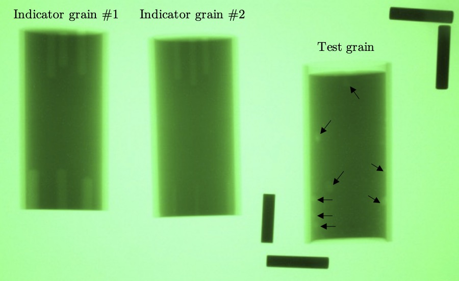
All propellant grains were imaged with an x-ray to inspect for voids or other defects within the grain. Every x-ray image collected had two indicator propellant grains within the field of view. These indicator grains were the same size as the test grain, and had holes of known diameter drilled into the ends at different radial locations in the grain. The indicator grains provide verification in every image that any voids present in the test grain with dimensions greater than the holes in the indicator grains should be visible in the image.
One of these x-ray images is shown below. The two indicator grains are on the left, and the test grain is on the right. Many voids are visible in the test grain, and are pointed out with arrows in the image. Propellant grains with significant voids were not used, since the voids would likely result in unpredictable propellant burning areas and motor chamber pressures.
Test Setup
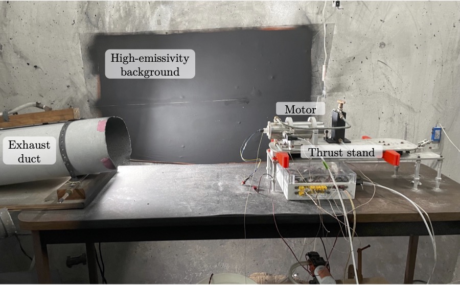
All motor tests were conducted in a reinforced concrete blast chamber located on MIT campus. The motors were mounted to a custom thrust stand (described here) positioned in front of a high-emissivity background. Thrust, chamber pressure, and exhaust plume radiant emission measurements were collected for each motor; the instrumentation for these measurements is discussed below. An exhaust duct was positioned downstream of the motor to collect the exhaust and vent it outside. This ventilation helped to prevent the exhaust gases from stagnating downstream of the motor and subsequently obstructing the exhaust plume radiant emission measurement. An image of the test facility is given below.
Instrumentation
Exhaust Plume Radiant Emission
The exhaust plume radiant emission was measured using a CI Systems SR-5000N spectroradiometer. The radiometer used liquid nitrogen cooled indium-antimonide (InSb) and mercury-cadmium-telluride (MCT) photovoltaic detectors that together are sensitive to radiation from 1.2 - 14.2 μm. A continuous variable filter sampled the different wavelengths during measurements into 379 wavelength bins across the spectrum. The spectrum was scanned at a rate of 1 Hz at the maximum instrument gain setting. Measurements are made relative to a floating internal blackbody in the radiometer.
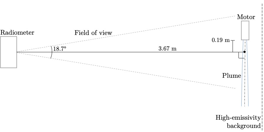
The collection optics of the radiometer had an 18.7° field of view. The radiometer was positioned 3.67 m away from the center axis of the exhaust plume, and the center of the optics were positioned to be 0.19 m downstream from the nozzle exit plane of the motor. The positioning was chosen to keep the plume within the center third of the field of view, which has a flatter measurement response from the radiometer optics. The concrete wall behind the motor served as a thermally stable background, given its large thermal mass. The wall was painted with a high-emissivity paint to create a high-emissivity background for the radiant emission measurement, which prevented any reflection of radiation from the room or plume that might have altered the measurement. The figure below illustrates the positioning of the radiometer with respect to the motor.
Thrust and Chamber Pressure
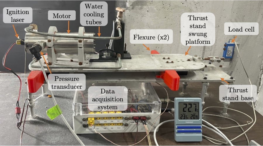
Thrust is measured using an Omega LCEB-5 load cell with a rated capacity of 5 lbf (22 N). The load cell is connected to a swung platform on a thrust stand1, shown below, on which the motor is mounted. Flexures support the swung platform, which constrain the platform to have one degree of freedom in the thrust direction. The linkage between the swung platform and the load cell uses a double-ball joint that only constrains movement in the thrust direction.
Chamber pressure was measured using an Omega PX119-600AI pressure transducer with a 600 psi (4.1 MPa) maximum pressure. The pressure transducer was mounted through the wall of the motor case. Excess volume in the connections between the pressure transducer and the motor case was packed with low thermal conductivity silicone grease to protect the pressure transducer from the hot combustion gases of the motor. The pressure transducer mounted to a motor can also be seen below.
Results
The radiant intensity and chamber pressure measurements for the core test matrix of four static fires (SF) are shown below. These four static fires are denoted SF4, SF5, SF6, and SF7. The pressure traces for SF4, SF6, and SF7 are relatively flat, which is the desired behavior for an end-burning motor. SF5 shows an initial peak in pressure, which eventually decays to a relatively steady chamber pressure, although the trace is still slightly regressive. The peak and decay are most likely due to the use of a relatively large starter grain used for igniting the propellant, which wasn’t used for the other motors. This starter grain created an initial increase in burning area before being consumed, which explains the initial peak in chamber pressure. Its possible that the hotter, faster burning commercial propellant starter grain caused the main propellant grain near the starter grain to momentarily burn faster than the rest of the propellant surface, altering the propellant surface geometry such that the rest of the pressure profile was slightly regressive.
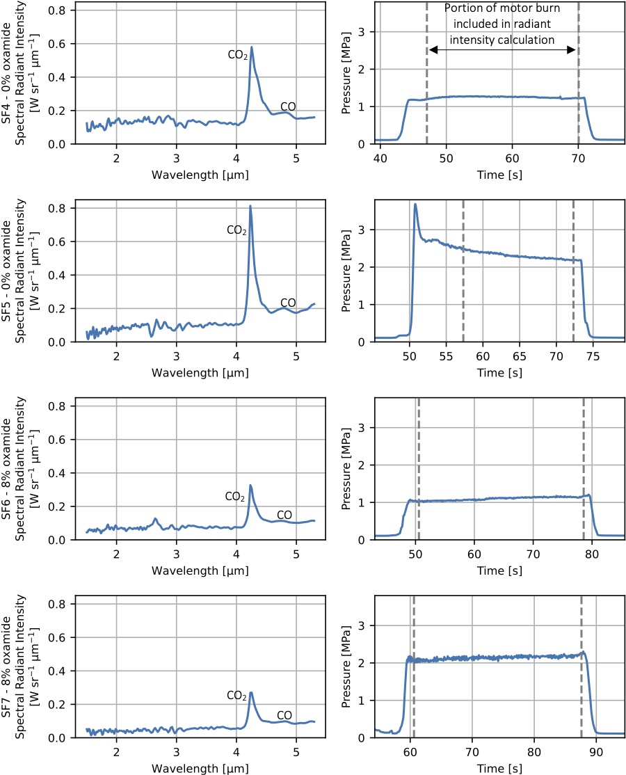
Emission bands in the radiant intensity spectra for the motors correspond to the combustion products in the motor exhaust. The radiant intensity spectra for SF4-SF7 each have a strong peak at 4.3 μm. This peak is due to the CO2 in the exhaust plume, which has a strong molecular emission band centered at 4.3 μm. A weaker peak at 4.7 μm can also be seen, which is due to CO emission. The measurements at wavelengths less than 4 μm for each motor test are unfortunately noisy. Measuring the radiant emission of these small, slow-burning solid rocket motors required operating the spectroradiometer near its lower sensitivity limit. Even at the maximum gain setting, the exhaust plume contrast measurements used, at most (at the 4.3 μm CO2 band where the signal was strongest), 7.7 % of the dynamic range of the detector. For a larger motor with more emission, a band centered at 2.7 μm due to both H2O and CO2 and a band centered at 3.5 μm for HCl would be expected, given the expected combustion products in the motor’s exhaust. However, these weaker emission bands are not very pronounced for these small, low-thrust motors.
Much of the discussion on this page was borrowed from my PhD thesis.
-
The thrust stand was originally designed and built by Dr. Matthew Vernacchia for his doctoral thesis work. Modifications were made for this work. ↩