
Small, Long Endurance Ceramic Rocket Nozzle Development
I developed two different nozzle designs to address the challenging requirements for small, long-endurance rocket motors. This work includes:
- designing and manufacturing a two-piece nozzle design with a 3D printed cellular ceramic insulator using a stereolithography process;
- designing a single-piece nozzle design with the novel application of a machinable alumina-silicate material;
- evaluating ceramic thermal shock properties with water quench experiments;
- testing of the novel single-piece nozzle in a solid rocket motor instrumented with thermocouples; and
- analysis of the measured nozzle thermal data and comparison with simulated results.
Overview
Typical solid rocket motors rely on transient methods – such as ablation or heat-sinking – for managing heat transfer through the nozzle and maintaining acceptable temperatures in the motor case. A large motor can use an ablative nozzle, which might erode by several millimeters during the motor burn; since these few millimeters represent only a small fraction of the nozzle throat diameter, the motor’s thrust barely changes. A short-duration motor can rely on simple heat-sinking methods; the heat capacity of the motor case is often sufficient such that the heat transferred to it during the short motor burn does not unreasonably increase the temperature. However, these methods do not work for a small, long-endurance solid rocket motors. The nozzles for these motors require a steady-state insulation technique to ensure the temperature limits of the motor case material are not exceeded.
Nozzle material and design considerations
These nozzles are designed for a small, rocket-powered, low-thrust, long-endurance aircraft concept described here. This aircraft concept utilizes a long-endurance solid rocket motor with a specially developed class of slow-burning solid rocket propellants.
The materials and design for these nozzles should be chosen to provide a high maximum service temperature (the operating temperature of the nozzle is 1500 - 2000 K), a low thermal conductivity (< 5 W m-1 K-1), and good thermal shock properties with a critical fracture temperature change \(\Delta T_f\) > 1000 K.
Nozzle 1: Two-piece ceramic nozzle with 3D printed cellular ceramic insulator
This nozzle was designed in collaboration with Dr. Matthew Vernacchia, and more information can be found in our paper here.
Dr. Vernacchia and I designed a two-piece nozzle configuration with a 3D printed cellular ceramic nozzle insulator. The two-piece nozzle configuration, illustrated generally in the figure below, uses a nozzle insulator and contoured nozzle insert which are manufactured separately and then bonded together with a silica adhesive. The contoured nozzle insert is turned from boron nitride rod.
The 3D printed ceramic insulator is based on a hexagonal honeycomb that is wrapped around a cylinder, as shown below. This design concept has several advantages: the honeycomb structure reduces the stiffness of the nozzle, making it more resistant to thermal shock; thin walls reduce conductive heat transfer radially through the part; small cells reduce convection; and the multiple layers of cell walls create redundant gas seals.
The design is compatible with a stereolithography printing process, and was ultimately manufactured using a Form 2 stereolithography printer. The part is printed using the Formlabs Silica resin, which consists of a photosensitive polymer resin filled with silica particles. After printing, the part must be subsequently fired in a kiln to burn off the polymer and sinter the silica particles together. This results in part shrinkage, and so the part must be oversized when printing. An image of a printed insulator with a bonded contoured nozzle insert is shown below.
The nozzles were manufactured and tested successfully in small, long-endurance test motors. However, there are some manufacturing and performance drawbacks for this nozzle design.
Boron nitride is a relatively soft material, and consequently the tested nozzles using the boron nitride inserts showed nozzle erosion, which decreases the expansion ratio and specific impulse of the motor.
The 3D printing process for the cellular ceramic insulation was also unreliable. The thin cell walls were printed near the minimum resolution of the printer for this resin, which lead to inconsistent wall thicknesses. The silica filled polymer used for the printing process was especially viscous, and often led to failed prints where the insulator broke off from its supports mid-print. The insulators had inconsistent material shrinkage during the kiln firing process, which varied between 14 - 20 % in the \(r \theta\) directions and 15 - 22 % in the \(z\) direction for 29 different nozzle insulator iterations. The use of a two-piece configuration inherently requires an additional machining step and a bonding step than would be required by a configuration where the nozzle insulator and insert was a single piece. Additionally, the thin silica was partially transparent to infrared radiation, which increased the heat transfer through the nozzle.
Nozzle 2: Single-piece alumina-silicate nozzle
Following the manufacturing difficulties described described in the previous section, I developed a new single-component nozzle design manufactured from an alumina-silicate material. The material and design for this nozzle were specifically chosen to simplify manufacturing, and address many of the manufacturing issues described previously. The single-component nozzle configuration is shown generally below.
The alumina silicate material used is the naturally occurring alumina silicate mineral pyrophyllite, and is often known by the trade names of “Wonderstone” or “Lava”. The alumina silicate material has a low thermal conductivity in the range of 1.3 - 2.5 W m-1 K-1 and a softening temperature of 1873 K 1.
Thermal shock properties for materials are typically indexed with a thermal shock resistance parameter \(R_s\). For Biot number2 \(\gg 1\), thermal shock resistance is defined as:
\[R_s \equiv \frac{\sigma_{flex} (1 - \nu)}{E \alpha_{LE}}\]where \(\sigma_{flex}\) is flexural strength, \(\nu\) is Poisson’s ratio, \(E\) is Young’s modulus, and \(\alpha_{LE}\) is linear coefficient of thermal expansion 3. Thermal shock resistance is related to critical fracture temperature change \(\Delta T_f\) with:
\[\Delta T_f = R_s S\]where \(S\) is a shape factor (typically of order unity), dependent on the part geometry and material property variation within a part. For thick-walled hollow cylinders with constant material properties, the shape factor \(S\) is a function of the ratio of inner and outer radii, and have values near or greater than 2 3.
The alumina-silicate has a low coefficient of thermal expansion \(\alpha_{LE} = 3.6 \times 10^{-6}\) K-1 and reasonable flexural strength of \(\sigma_{flex} = 69\) MPa which following the definition of \(R_s\) is suggestive of reasonable thermal shock properties 1. Some simple experiments to gain more insight on the thermal shock resistance and critical fracture temperature change of the material were conducted, and are described in a following subsection.
The alumina-silicate material is purchased in a semi-fired state, and importantly it can be machined with standard tooling in this state. The material must be subsequently fired in order to achieve the full mechanical and thermal properties. The alumina-silicate expands in all dimensions when fired, and so all machined dimensions before firing must be under-sized accordingly. 11 nozzles were machined in total for this project, and the average material expansion after firing was \(\mathrm{2.56 \pm 0.13 \%}\).
The nozzle is bonded to the motor case using a high-temperature flexible silicone adhesive. The nozzle and motor case are designed with a tapered interface with the motor case such that if the material expansion is slightly different than anticipated, the nozzle can still seal against the motor case.
Thermal shock experiments
A series of simple thermal shock experiments using water quenching were conducted on the alumina silicate material 4. Four samples of alumina silicate material were prepared from 2.5 cm diameter rod. The samples were cut on a bandsaw in 2.5 cm lengths and edges were sanded to remove any sharp protrusions resulting from the cut. The samples were then fired in a kiln to achieve their full-fired material properties.
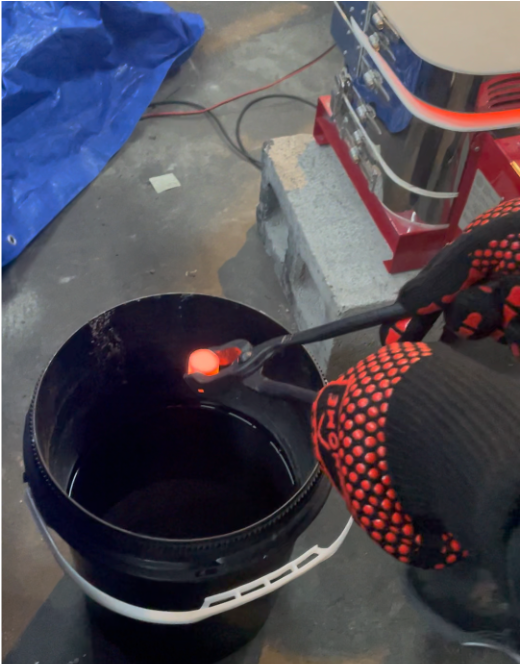
The prepared samples were then heated in a kiln to a series of incremental temperatures. After the samples were heated and thermally soaked at the desired temperature, they were removed from the kiln and quenched in a room temperature water bath as shown below. This quenching procedure provides an analogous thermal scenario to the nozzle: when the sample is quenched, the inside of the sample will be hot and the outside of the sample will be cool, as is the nozzle on motor startup. After the samples were quenched, they were visually inspected for surface cracks. If no cracks were present, the samples were heated in the kiln to the next temperature.
Samples were tested up to a maximum \(\Delta T\) of 1000 K. None of the samples cracked at or below this temperature. This suggests that \(\Delta T_f \gtrsim\) 1000 K for the alumina-silicate material.
Nozzle testing
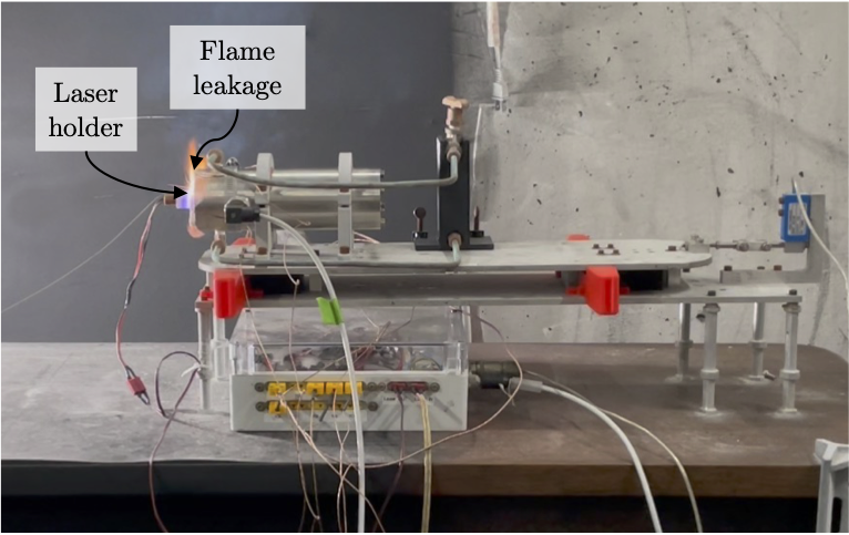
The alumina silicate nozzles were used in eight static fires of a research motor. This research motor, discussed further here, uses an end-burning solid rocket motor with a laser ignition system. An image of one of these nozzles being used in a static fire is shown below. In the first seven static fires, the nozzle was water-cooled by flowing water in a channel around the nozzle. These tests are still valuable for evaluating thermal shock performance of the nozzle, but are not suited for evaluating thermal insulation performance. In the eighth static fire (“SF8”), water was not flowed through the water cooling channel. This test is more suited to evaluating thermal insulation performance. Thermocouples were embedded in the bond line between the nozzle and aft closure for SF8 to evaluate the insulation performance, which will be discussed in the next subsection.
Nozzle thermal insulation performance
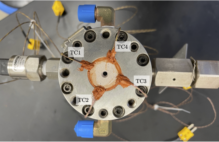
In SF8, four Type K thermocouples were embedded in the bond line between the nozzle and the aft closure, as shown in the image below. Slots were dremelled into the outer surface of the nozzle to accommodate the weld bead and wire of the thermocouples. The weld bead was potted into the silicone adhesive in the prepared slots at the bond line, approximately 2 mm from the aft face of the nozzle. The thermocouple wires were routed out the aft end of the motor and secured with a hose clamp around the outside of the motor. The thermocouple wires were potted with extra silicone at the aft face of the motor to protect them from the motor exhaust gases.
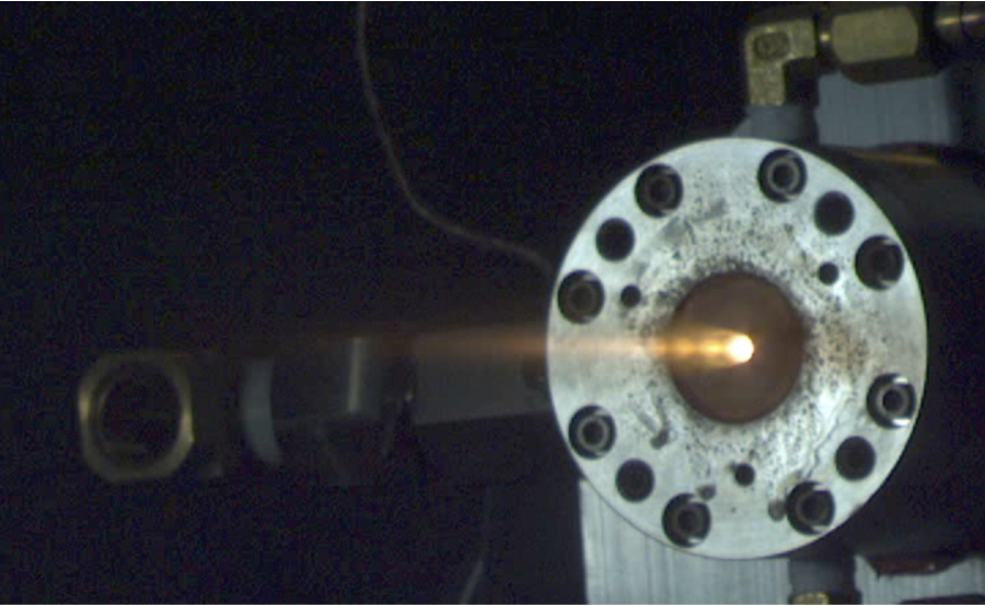
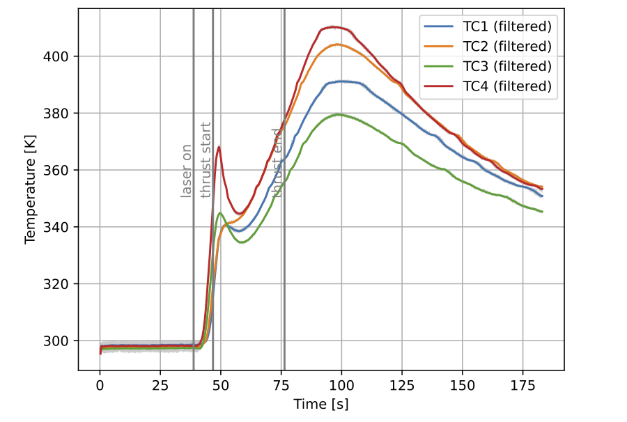
The measured bond line temperatures of the four thermocouples is shown below. The initial sharp rise and peak in measured temperatures after motor “laser on” was due to a design issue with the laser ignition system that caused flames to leak around the aft face of the motor before laser holder fell away from the motor. This flame leakage around the laser holder is shown in the second figure below. The excess heat from the flame leakage was distributed throughout the large heat capacity of the motor case after the laser holder fell away near “thrust start”, and so the temperature decreased temporarily at that time. Then, the temperature rose again as the material and thermocouples were actually being heated by the heat transfer through the nozzle. The spread in the thermocouple measurements is possibly due to slight variations in the positions of the thermocouple weld beads or features in the motor case that are not radially symmetric (i.e. water cooling ports, rupture disc assembly, pressure transducer) that effect the thermal properties of the material around the thermocouples unevenly.
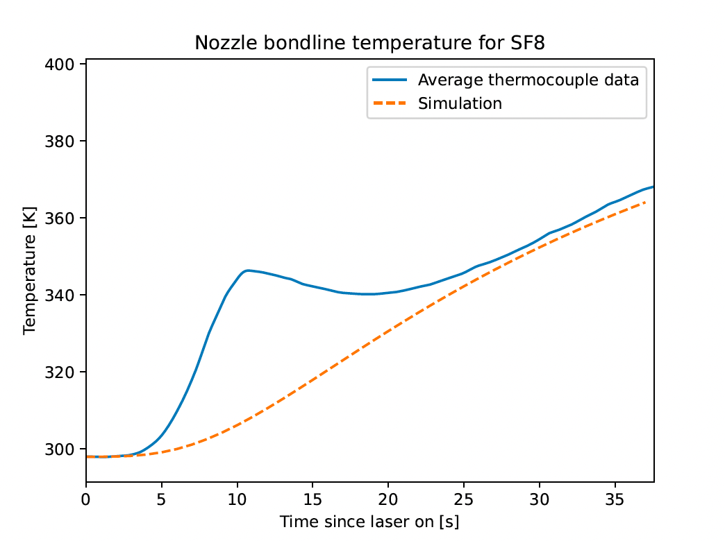
A transient thermal simulation of the nozzle was run to compare against the measured thermocouple data from SF8 and verify the alumina-silicate nozzle material thermal conductivity. A 2D axisymmetric finite element analysis was used to simulate the temperature at the nozzle bond line. The nozzle internal convection coefficients were based on a separate computational fluid dynamics analysis (see here, section 9.2.3.1), which were adjusted for the chamber pressures in this research motor using the Bartz heat flux correlation. An external convective boundary condition with an adiabatic wall temperature of 298 K and a convection coefficient of 10 W m-2 K-1 is assumed to account for natural convection at the outer surface of the motor. The alumina silicate is assumed to have a constant thermal conductivity of 2.5 W m-1 K-1 1.
The simulated and averaged measured bond line temperatures are plotted below for times between “laser on” and “thrust off”. The simulation shows a monotonic rise in temperature. This is the expected behavior before burnout as the heat transferred from the hot combustion gases flowing through the nozzle soaks through the nozzle. Again, the thermocouple data shows an initial peak due to the flame leakage around the laser holder before it released. The temperature then decreases after the laser holder falls away and the excess heat is distributed through the large heat capacity of the motor case. Then, the temperature increases again as the heat from the hot combustion gases soaks through the nozzle to the bond line. After the initial peak in thermocouple temperature due to the flame leakage, the agreement between the thermocouple data and the simulation is surprisingly good. This suggests that the alumina-silicate material is behaving as expected, and has acceptable thermal performance in the context of a rocket nozzle for a small, long-endurance motor.
Nozzle cracking
Despite the results of the thermal shock experiments discussed previously, the nozzles cracked in all eight static fires of the research motor. All cracks were in the \(rz\) plane of the nozzles (see here for nozzle coordinate directions), which is consistent with cracking to relieve stress from thermal shock. An image of these cracks for a nozzle is shown below.
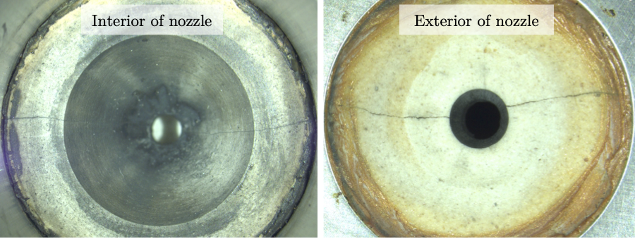
There are several possible explanations for why the thermal shock water quench experiments discussed previously did not show material cracking, while the nozzle motor tests did. Some possible explanations are that the peak temperature change across the nozzle on motor startup was greater than the 1000 K benchmark used in the thermal shock experiments, or that machining defects left stress concentrators in the nozzles that weren’t present in the thermal shock test samples. Despite the crack formation in the nozzles, the tapered interface between the nozzle and the aft closure meant that the pressure load on the nozzle from the combustion gases forced the cracks to seal. Because any leak area through the crack is significantly smaller than the nozzle throat diameter, it is not expected that there was any significant pressure loss due to the cracks.
Much of the discussion on this page was borrowed from my (not yet complete) PhD thesis.
-
Source: Wonderstone Technical Datasheet ↩ ↩2 ↩3
-
Biot number is defined as \(\beta \equiv h l / k\), where \(h\) is convective heat transfer coefficient, \(k\) is thermal conductivity, and \(l\) is characteristic length. \(\beta \gg 1\) indicates that there are strong temperature gradients within a body due to convection at a surface, and that material conductivity is not large enough to distribute heat away from the surface. For the nozzles in this work, \(h \approx\) 3000 W m-2 K-1, \(k \approx\) 2.5 W m-1 K-1, and \(l \approx\) 1 cm, and so \(\beta \approx 12 \gg 1\). ↩
-
Source: John B. Wachtman, W. Roger Cannon, and M. John Matthewson. “Mechanical Properties of Ceramics (2nd Edition)” Publisher: John Wiley & Sons. issn: 978-0-471-73581-6. ↩ ↩2
-
I’d like to thank MIT undergraduate researchers Insuh Na and Justin Schiavo for their help in setting up and conducting these experiments. ↩