Level 3 Rocketry Certification
Overview
I designed, built, and flew a high-power rocket as part of the National Association of Rocketry Level 3 Certification program. This certification involves building, flying, and successfully recovering a rocket that safely use an M impulse class or higher commercial solid rocket motor. The rocket design, performance analysis, and recovered vehicle are inspected by a certification committee.
General Description of Rocket and Flight Operation
The rocket is a 6-inch diameter, 99-inch long, custom build rocket. The airframe consists of phenolic tubing with a 2-ply fiberglass overwrap and a fiberglass nosecone. ½ inch plywood bulkheads and centering rings are used throughout. The fins are ¼ inch plywood with a 2-ply fiberglass tip-to-tip layup. The rocket flew on a CTI M1230 motor.
The rocket had a dry weight of 25.0 lbs, and an expected apogee 8,090 feet. The rocket utilized a dual-separation, dual-deploy recovery scheme: the rocket separates twice in two different events during its descent, and a different parachute is deployed during each of those separations. The airframe aft of the avionics bay houses the drogue parachute (a small parachute deployed during the first rocket separation event), and the airframe forward of the avionics bay houses the main parachute (a large parachute deployed during the second rocket separation event).
Rocket Construction
Airframe Body Tubes
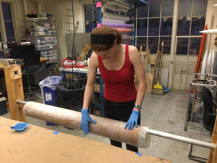
The tubes are made from 6” diameter phenolic tubing from Public Missiles. A two-ply fiberglass overwrap using the West Systems epoxy system was completed to reinforce the airframe. The fiberglass was first spread on a piece of mylar and then coated in epoxy. The wet fiberglass was then rolled onto the phenolic tubing, and was smoothed to eliminate bubbles forming beneath the layup. Peel-ply was applied at the completion of the layup, and the layup was cured in atmosphere for 24 hours. The layup can be seen completed on a mandrel below.
Bulkheads, Centering Rings, and Fins
Bulkheads, centering rings, and fins were laser cut using ¼ inch plywood. Bulkheads and centering rings were doubled, and epoxied together using Proline epoxy. The bulkheads and centering rings were clamped together and left to cure for 24 hours.
Motor Mount Tube Construction and Mounting
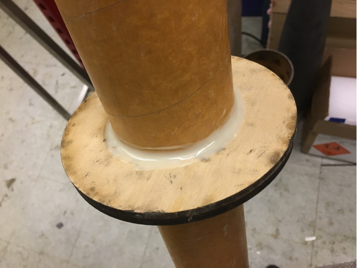
Two centering rings forward of the fins were installed first on the motor mount tube, with the lower center ring coincident with the tops of the fin tabs. The motor mount tube surface was prepared by sanding with 400 grit sand paper to help the epoxy adhere properly. Fillets were applied at all interfaces between the centering rings and the motor mount tube, as shown below.
Additionally, a u-bolt for recovery webbing attachment was installed in the forward most center ring. The u-bolt was epoxied in to make it a permanent installation.
The motor mount tube was installed in the main airframe. Again, the inner surface of the airframe was prepared with 400 grit sand paper to help the epoxy adhere better. Fillets were applied at all accessible interfaces between the airframe and the centering rings.
Fin Mounting Methods
Through-the-wall fin mounting methods were used. Carefully measured slots were cut in the airframe using a dremel to mount the fins to the motor mount tube. A jig was 3D printed to enable even and perpendicular mounting of the fins with the airframe.
Fillets were applied with epoxy at every interface between the fins and the airframe. In image of some of the internal fillets between the fin tabs and motor mount tube are shown below.
A two-ply tip-to-tip fiberglass layup was done across each of the fin pairs. The first ply was cut to be slightly smaller than the fins. The second ply was cut slightly larger than the fins, and then trimmed and sanded flush to the fins after application and epoxy cure. The cut fiberglass plies were coated with epoxy, and then applied to the surface of the fins, which were prepared with 400 grit sand paper. An image of one of these tip-to-tip layups is shown below.
Additionally, to reinforce the fin mount to the airframe, polyurethane expanding foam was used to fill the spaces between each of the three fins, as shown below. This is important to ensure the fins are not damaged when the rocket lands, which can often exert large moments on the fins.
Nosecone Bulkhead and Ballast Installation
The nosecone bulkhead attachment was done in two pieces. An outer ring was first installed in the nosecone, creating an attachment point for the recovery bulkhead, but still enabling access to the nosecone. The outer ring was attached using epoxy. The outer ring is inserted above the nosecone shoulder, such that there is a mechanical stop providing reinforcement to the ring as well. Fillets additionally reinforce the mounting from both sides.
An inner bulkhead then bolts into this ring with 8 4-40 screws. A u-bolt is attached to this bulkhead to provide an interface for recovery webbing. This bulk head can be seen below.
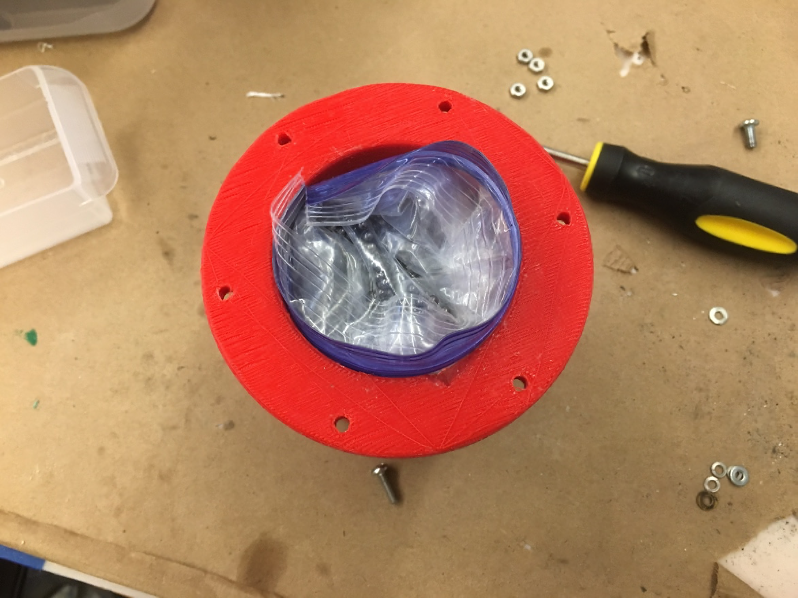
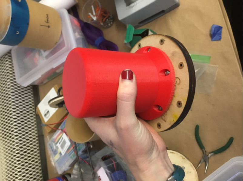
Ballast was required for this rocket, both to ensure its stability and keep it under the maximum altitude allowed by the launch field. The ballast was attached to the removable inner bulkhead, and was mounted such that it would be attached inside of the nosecone. A container was 3D printed with a high infill density to provide a sturdy mounting point for the ballast. 3.5 pounds of lead shot is contained in this container in a plastic bag. This container is bolted onto the inner bulkhead with 6 4-40 screws, as shown below.
Recovery Package
Deployment Sequence
A dual-separation, dual-deploy scheme was utilized in the recovery of this rocket. The separations are initiated with e-matches in black powder pyrotechnic charges.
The aft portion of airframe houses the drogue chute. The primary drogue charge fires at apogee, and the backup fires after apogee with 3 second delay. The rocket separates at the interface between the avionics bay and the aft section of airframe.
The main chute is housed in the forward portion of the airframe. The primary charge fires at an altitude of 1000’. The backup fires at 900’. The rocket separates at the interface between the nosecone and the forward section of airframe.
Deployment Components
The drogue and main chutes are 2’ and 12’ Rocketman brand chutes respectively. Nomex sheets are used to protect the parachutes and webbing from the black powder charges. 1’ nylon tubular webbing is used to attach parachutes and rocket components after separation. Loops were sewn at the end of each piece of webbing using a box seam.
Both the forward and aft section of airframe have 28’ of webbing, and parachutes are attached six-feet along the webbing from the rocket separation point. All interface attachments are done with 1000-pound quicklinks.
Four 4-40 nylon shear pins are used at each interface. Each compartment as two ¼ inch holes to allow for pressure relief during launch and prevent premature separation of the rocket at the shear pins due to pressure forces.
The Rocketman recommended descent rate charts were utilized to determine the descent rate. According to the manufacturer, it was expected that this rocket would descend at a safe rate of 16 ft/s.
Control Devices
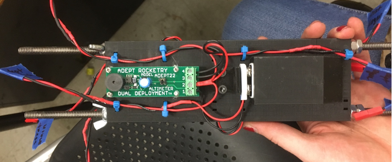
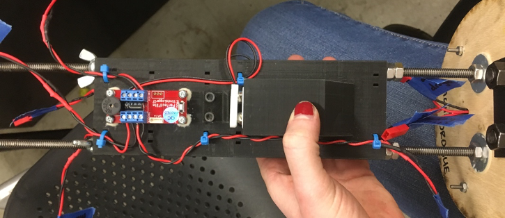
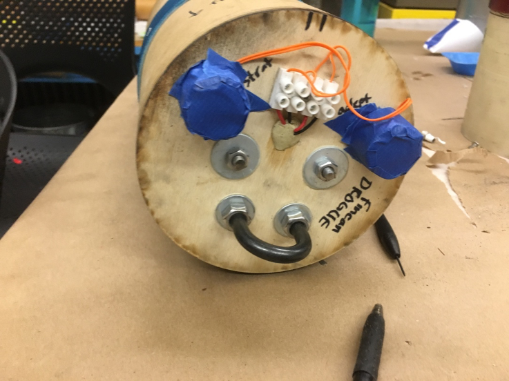
The primary altimeter used is a StratologgerCF, and the backup is an Adept22. Both utilize barometric altitude sensing with a resolution of 1 foot. Schurter rotary switches mounted to the switch band on the outside of the avionics bay are used to safe/arm the altimeters on the launch pad. This external mounting of the switches allows for easy arming/safing of the altimeters. Each altimeter is powered by an independent 9V battery. Altimeters and batteries are mounted to a 3D printed sled. This sled was in turn mounted to two 1/4-20 threaded rods that ran through the avionics bay. The altimeters mounted to the sled are shown in the images below.
Pyrotechnic devices were tested successfully in a full-powered ground test with 3.9 grams of black powder in each separation charge initiated by e-matches. Packed charges on the avionics bay bulkhead can be seen below.
Stability Evaluation
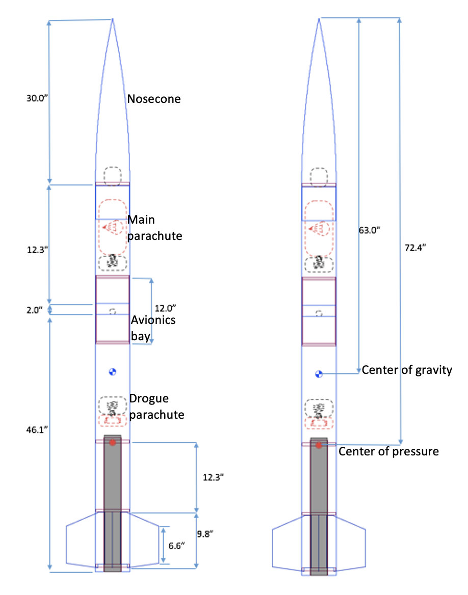
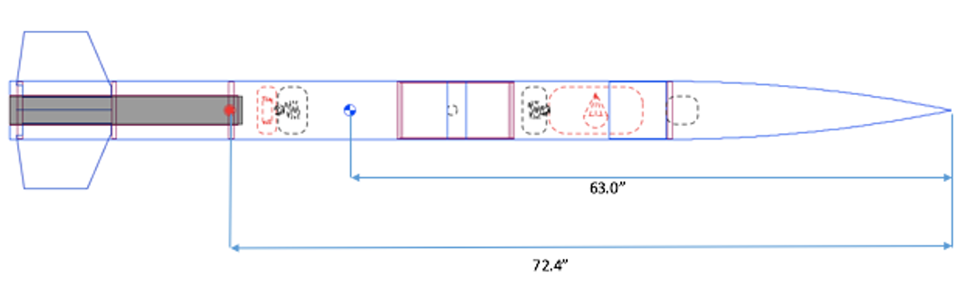
OpenRocket was used to determine the CP location. The CG location was physically measured by assembling the rocket and finding the balance point. Both these quantities are shown in the image below. Assuming a 12’ launch rail, this gives a stability of 1.6 calibers at the rail-end velocity.
Flight
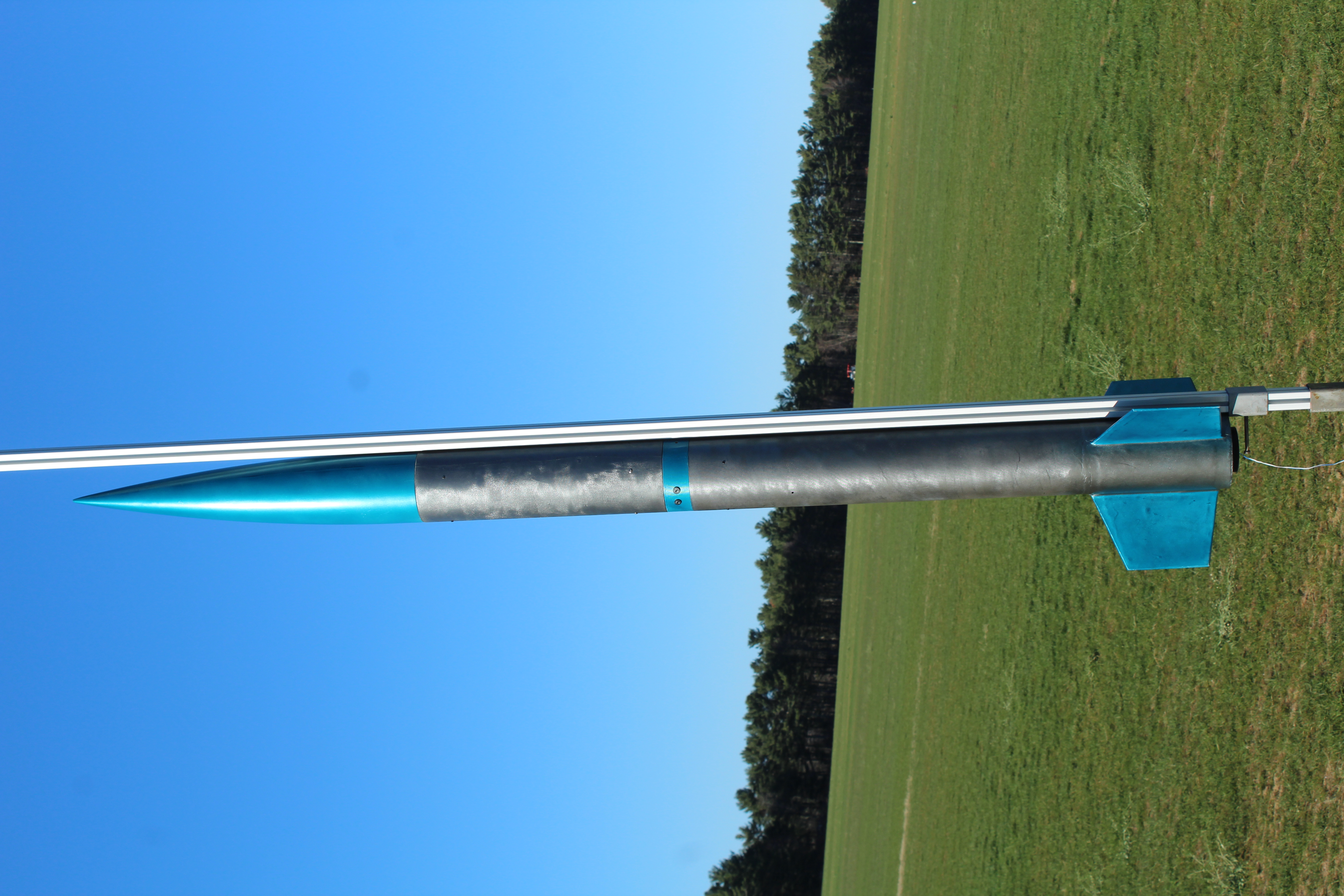
The rocket was successfully flown and recovered at a launch site in Berwick, Maine. Before launch, the rocket was assembled, inspected, and mounted to the launch rail. The altimeters were armed and the motor igniter was installed. A camera was mounted to the outside of the airframe in a 3D printed aeroshell to capture onboard footage of the launch (shown at the top of this page). A picture of the complete rocket on the launch rail is shown below.
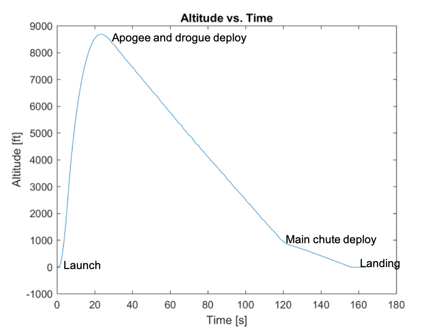
The parachute deployments occurred as planned, and the rocket was recovered safely in re-flyable condition. An image of the separated rocket in descent under the main parachute is shown in the figure below.
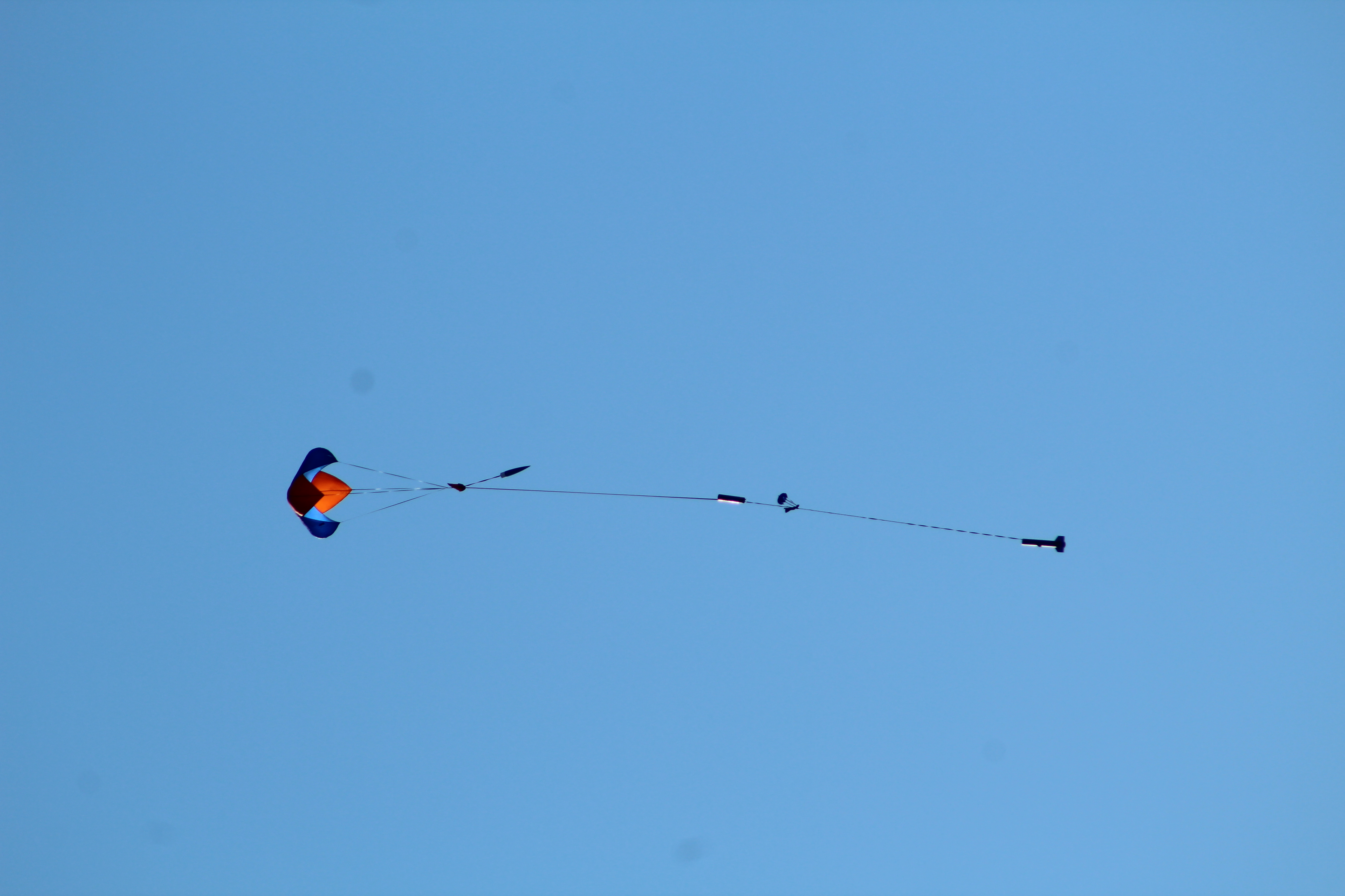
According to flight data from the StrattoLogger altimeter onboard, the rocket achieved an apogee of 8691’, and a maximum of speed of 1012 ft/s or Mach 0.96. The maximum altitude was within 8% of the predicted apogee of 8090’ estimated using OpenRocket.